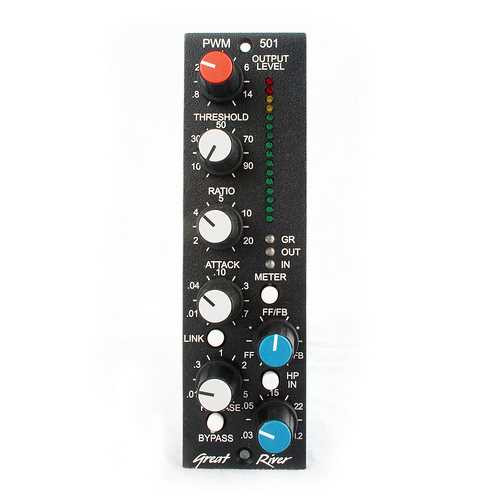
Full featured dyanmics control in any way you can imagine, pick up this 500 series compressor limiter today!
Output level control
This control sets the amount of make-up gain in the output amplifier. Use it to adjust the output signal level.
Threshold control
This control determines the portion of the signal that the rest of the sidechain will use to control the operation of the PWM-501. At low levels (0-50) the unit looks at all or most of the signal and acts as a compressor, at higher levels (50-100) it looks at peaks and the unit functions more as a limiter. The signal the threshold circuit is fed comes from the Feedforward/feedback control.
Ratio control
This control sets the percentage of the control signal sent to the PWM attenuator. Fully counterclockwise divides the signal the most, giving the lowest ratio. The actual ratio is approximate, as it is dependent on the variables of the threshold, attack and release times, as well as the setting of the feedforward/feedback control.
Attack time control
This control sets the initial charging speed of the time constant capacitor. The circuit feeding this capacitor is an absolute value peak detector, so it can be very fast. It can also generate unpleasant distortion if it is too fast for the signal content. Faster attack times are in the counterclockwise direction of the control.
Link switch
This switch will link the control voltage between PWM-501 units installed in a rack with the correct interconnections on the backplane bus. Any PWM-501’s connected via the link system will “or” their control voltages. One unit can be used to control all, or each can contribute. To defeat a units’ contribution to the bus, turn the local Threshold and Attack all of the way up, and the Ratio all the way down. This control voltage is unique to the PWM-501 and is not compatible with other manufacturers systems, so the bus must be broken up if other units are using it in the same rack. The bus used is Pin 6 of the backplane connector.
Release time control
This control sets the discharge speed of the time constant capacitor. Faster release times are in the counterclockwise direction of the control.
Bypass switch
This is a hard-wired bypass of the entire PWM-501 when depressed. The unit is also in bypass mode when the rack is unpowered.
High pass frequency control
This is a second order (12dB/octave) variable high pass filter that is inserted in the sidechain immediately after the feedforward/feedback blend circuit. When engaged it can filter out bass signals that might otherwise influence the action of the PWM-501.
High pass engage switch
The high pass filter circuit is engaged when this button is pressed.
Feedforward/feedback blend control
This control determines the source(s) and the blend of the sidechain signal. In the fully counterclockwise position the source of the sidechain signal is entirely the input audio, in the clockwise position the source is entirely the output signal. Most compressor/limiters use feedback to generate the sidechain signal. The control signal is always being modified by the action of the unit because of the previous signal. Feedforward operation uses the input audio to generate the sidechain signal, any previous operations do not have any influence on the operation of later signals. Very generally, feedforward is a faster, more aggressive operating mode, but it is easy to get too aggressive, especially with hot signals. Typically it is best to start working with a signal in the feedback mode, and then rotate the blend towards feedforward while readjusting the various sidechain controls to suit. Everything is interactive, and will need attention, but it is worth it because of the versatility.
Meter function switch and display LEDs
This switch determines the signal to the peak reading meter circuit. In the GR mode, the meter indicates 1dB of gain reduction for every LED lit. It indicates in a downward direction. In either the In or Out mode the meter indicates the signal level at the respective signal point. All green LED’s lit indicates a signal level of +4dBu at the XLR.


